Providing Hardfacing Solutions in Townsville

CORODUR HARDFACING

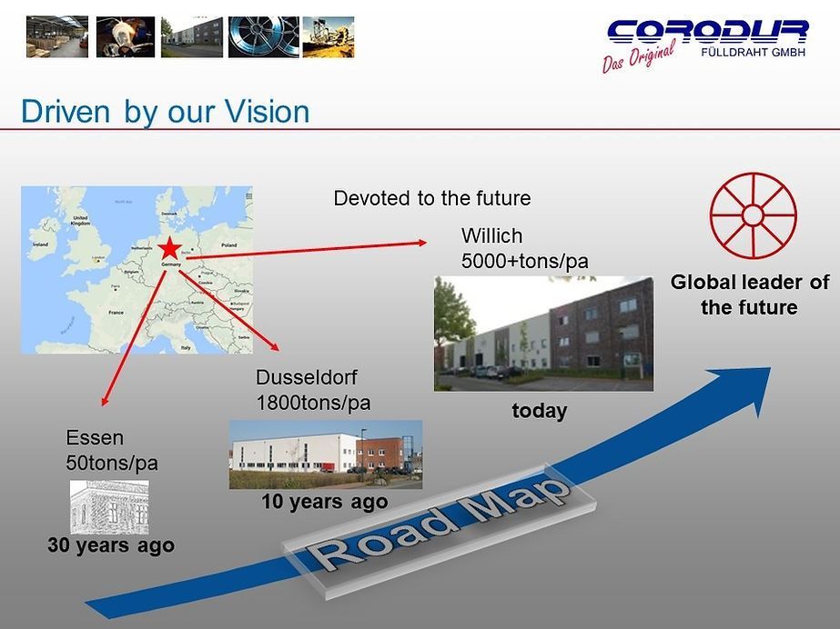
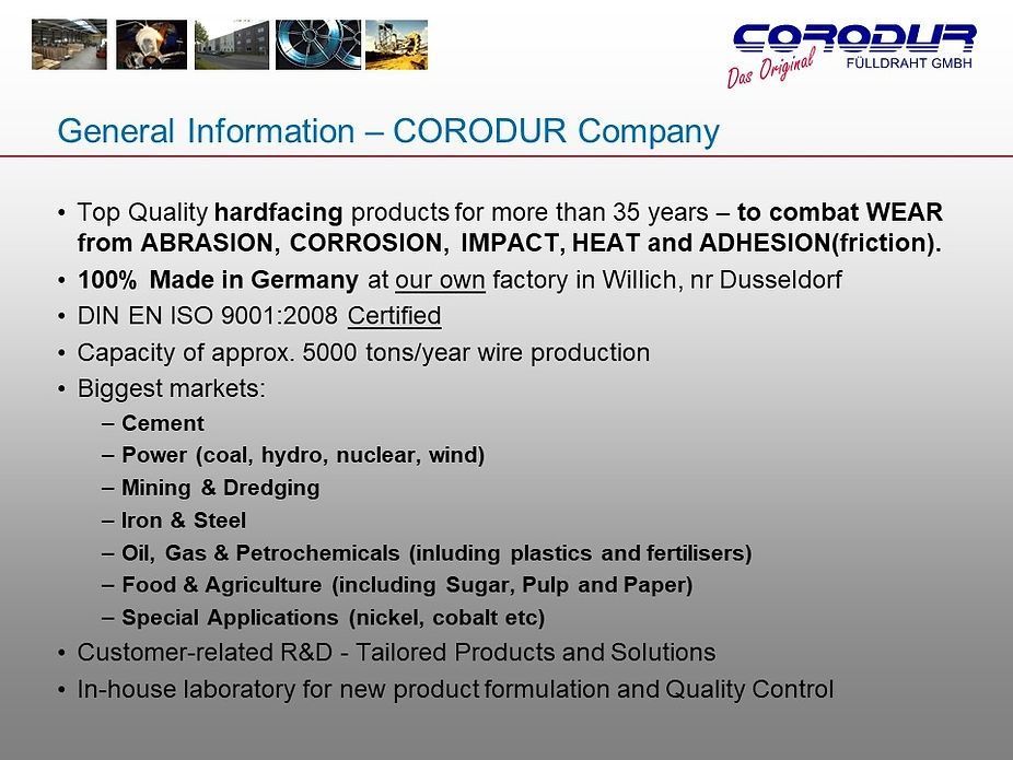
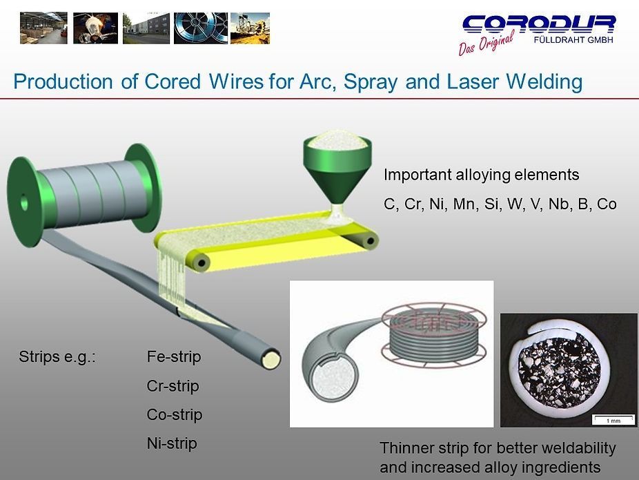
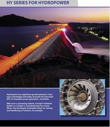
Corodur Fülldraht GmbH has been an industry leader in wear protection for over 30 years and is a specialist manufacturer of high-quality consumables for arc-welding and thermal spraying.
Quality Hardfacing Solutions
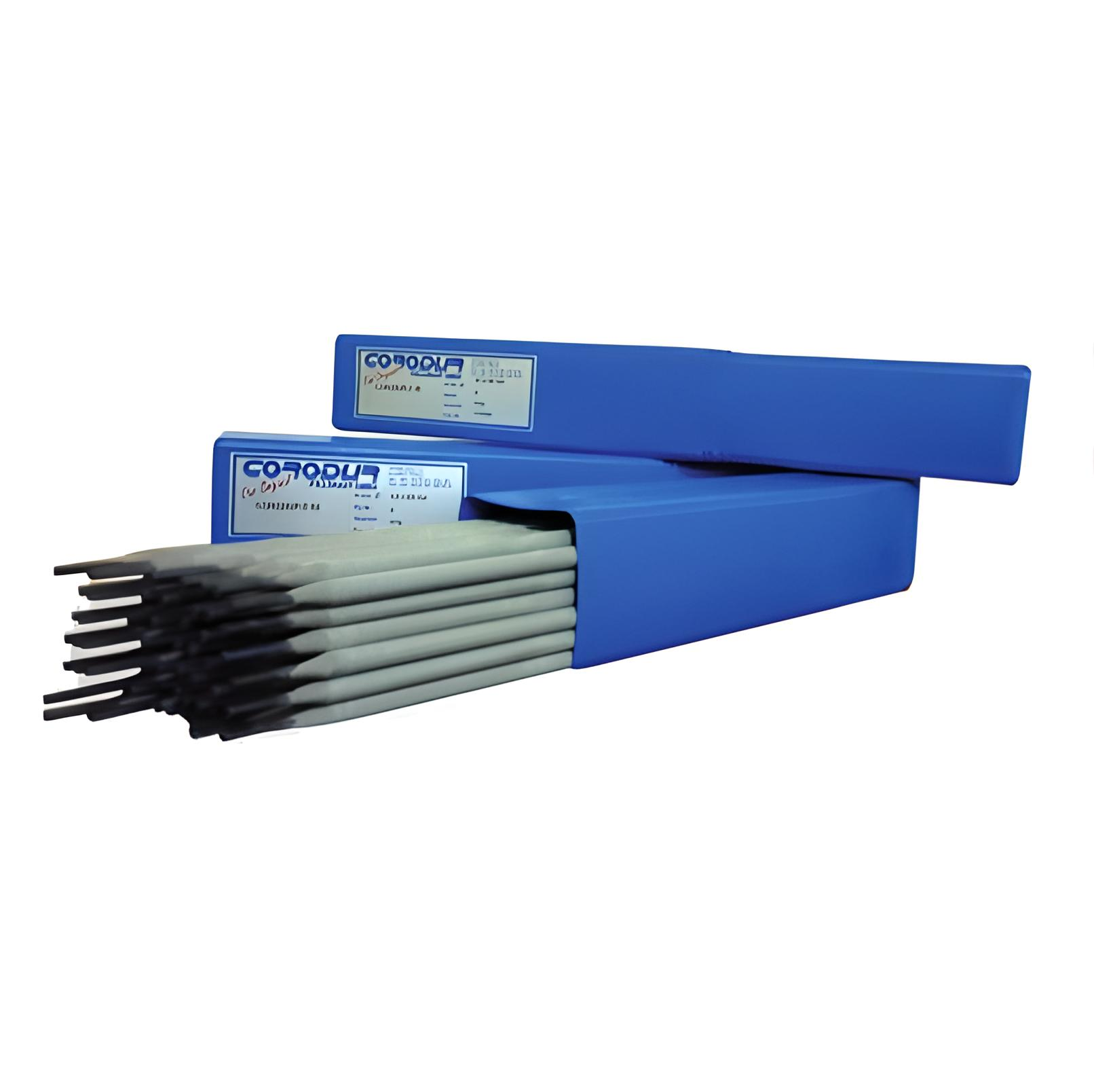
For top-quality hardfacing materials, CC Weld Solutions in Townsville is the clear choice. Catering to diverse industrial and commercial projects, we provide hardfacing welding wires, electrodes and more, ensuring durability and superior performance in every application. We supply:
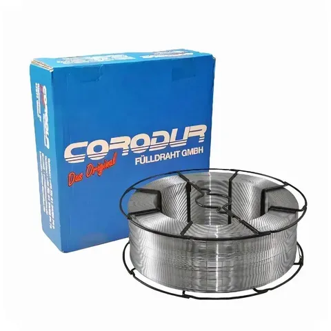
- Flux-cored wires
- Specialty wires
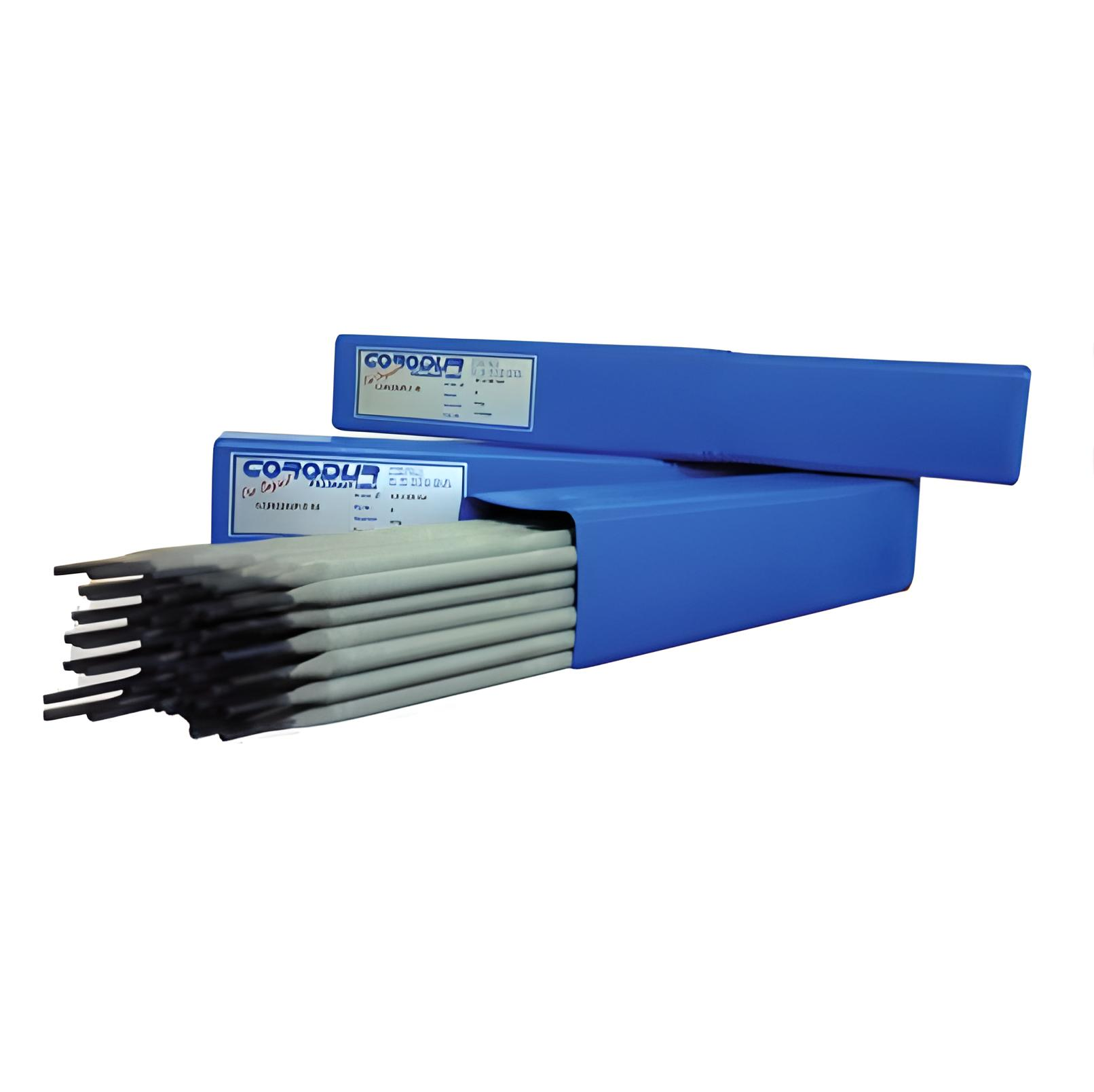
- Electrodes
- Tungsten carbide products
Call us on 0413 700 175 for product enquiries. We supply hardfacing materials for clients in Townsville, Mackay, Cairns, Mount Isa and surrounds.
Flux-Cored Wires
Unlock efficiency and versatility with our flux-cored wires, meticulously designed for superior welding performance. The flux-filled composition ensures optimal protection, minimising oxidation and enhancing weld quality in various applications. Whether you're tackling structural welding or intricate fabrications, our flux-cored wire stands as a reliable choice for achieving precise and consistent results.
Specialty Wires
Tailored to meet unique welding demands, our comprehensive range of specialty wires will ensure you have a steady flow of power. Whatever your industry, we will make sure your bespoke electrical wires meet the dimensions perfectly and adhere to safety standards.
Electrodes
Experience welding excellence with our meticulously crafted Electrodes. Engineered for precision and durability, these electrodes play a pivotal role in facilitating strong and reliable currents, meeting the diverse demands of welding applications across industries. Trust in our electrodes for consistent quality and performance.
HARDFACING/SPECIAL ELECTRODES
Catering to Diverse Applications
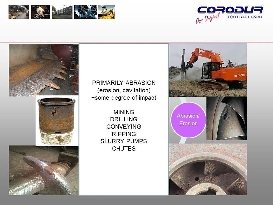
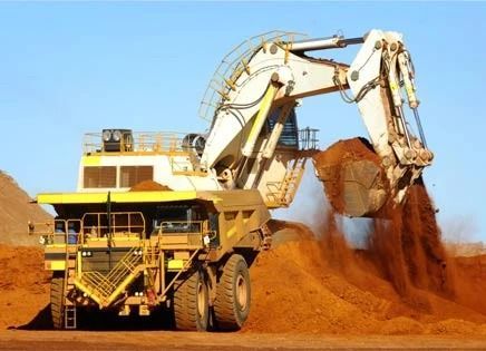
Our hardfacing materials are suitable for numerous applications and industries. Whether you require products for structural fabrication, mining or an agricultural project, our range ensures precision, reliability and efficiency.
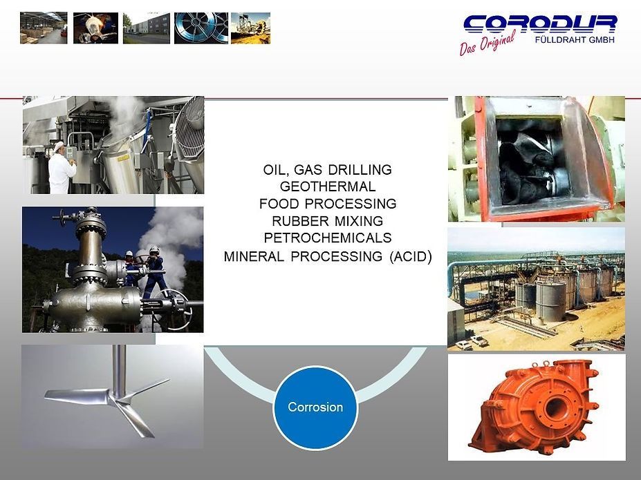
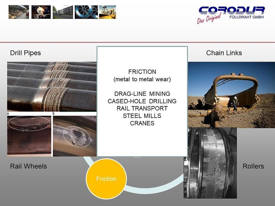
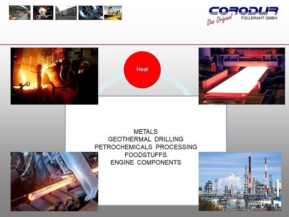
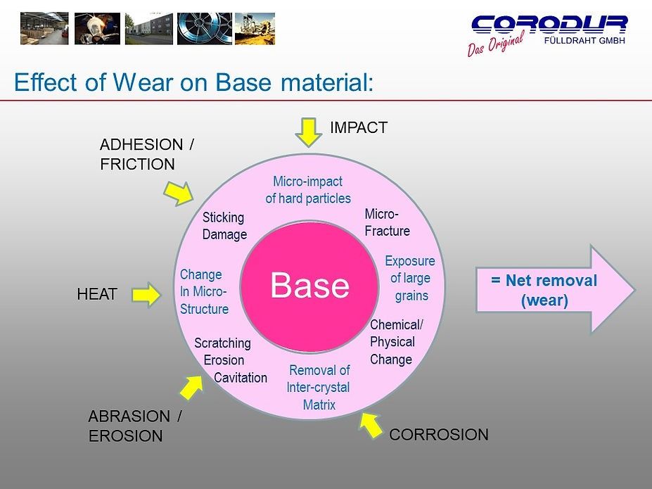
HARDFACING APPLICATIONS
Tungsten Carbide Products
Elevate the durability of your projects with our premium tungsten carbide products. Engineered for longevity and exceptional wear resistance, these products are ideal for demanding applications such as drilling and metal cutting. Choose our Corodur tungsten carbide lines for superior performance and lasting results in challenging industrial settings.
COROCARB NISE
Is a tubular electrode filled with fused tungsten carbide and a special nickel alloy for manual welding. This alloy is specially designed for application where extreme abrasion in combination with corrosion is encountered. Corodur-NISE can be overlayed on steel castings, nickel based and stainless steel alloys. The alloy combination of CORODUR-NISE is specially designed for items that are exposed to corrosive media and excessive wear conditions. The matrix is highly resistant to acids, lye’s and other corrosive media.
COROCARB FE
Is an open arc tubular wire filled with fused tungsten carbide (FTC) for semi-automatic application, where extreme abrasive wear is encountered. For hardfacing of low alloyed steels that have a maximum of 0,45% carbon (a higher carbon content could lead to cracking). Also for hardfacing and repairing tools and machine parts exposed to wear. The area to be hardfaced should be free of rust, scale, grease or other dirt. Depending on the base metal’s alloy and the size of the area to be hardfaced the advisable preheating temperature should be between 350-500 deg C (662-932 deg F). If the voltage and the welding current are kept on the lowest setting possible the tungsten carbide granular will be prevented from melting. During welding, position the arc that the weld metal is deposited in coarse droplets.
Hints & Tips
Select flux-cored wires based on welding requirements, considering factors like material compatibility and desired weld characteristics. For specialty wires, identify specific project needs such as corrosion resistance or high tensile strength. Choose electrodes based on welding method (stick, TIG, MIG) and material compatibility. When it comes to tungsten carbide products, assess wear resistance and hardness, aligning with project demands.
Hints & Tips for Hardfacing
It may surprise you to learn that 40% of every hardfacing success is not WHAT hardfacing material is applied. Rather, HOW it is applied.
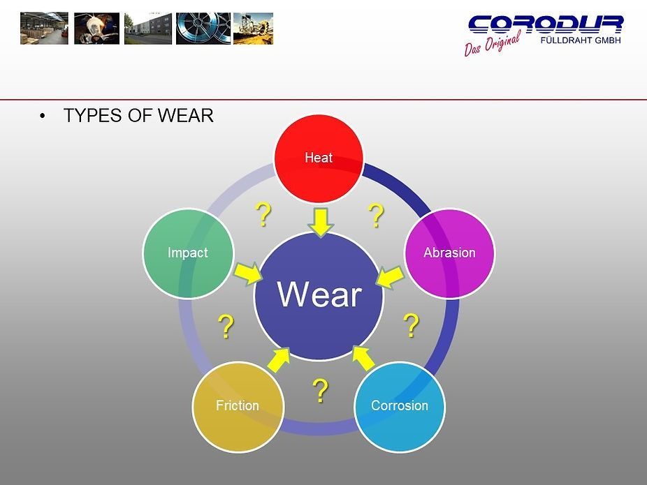
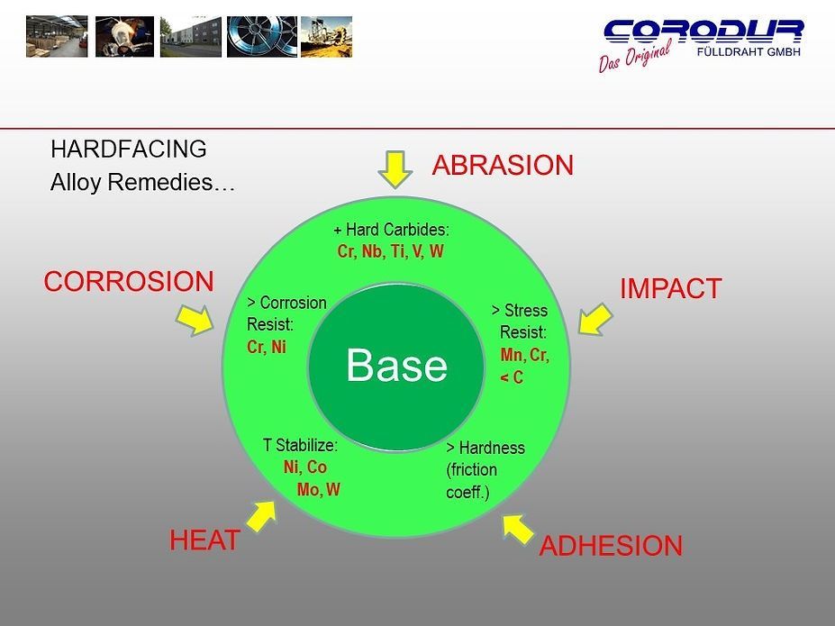
Consider for a moment that WEAR is a "dynamic force" that can change the direction of its action and level of force depending on how you try to limit it. Most high abrasion occurs at a high-angle and high-speed impact to the tool. Moving the incidence of abrasion to a low angle and dissipating the energy/force of impact makes a huge difference, regardless of the hardfacing chosen.
Like a grain on a beach, a wooden/concrete barrier designed to stop the eroding action of the sea. It is designed to reduce the angle of incidence of destructive waves to the beach and move the force along to a less critical part of the bay. That said, by moving the force along the beach, the hydrology engineers still have to be prepared for where the force does come ashore.
Likewise, with hardface-protection, successfully reducing the impact angle and moving the force along to another part of the tool, still creates an area of concern further along the tool that must be thought about and pre-empted!
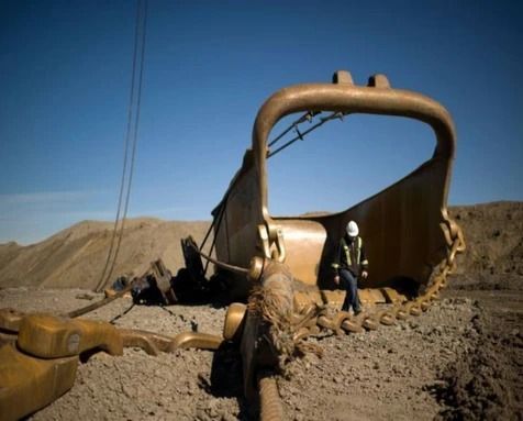
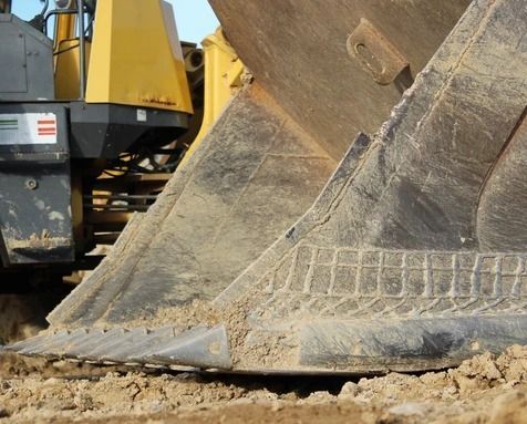
Now imagine you are trying to hardface a digger tooth or a point or a bucket lip or conveyor screw or mixer paddle. Think hard about the abrading forces. Where they come from, how they strike the tool, how powerful they are. Ideally look at a spent/used item and see how it has worn. Consider that your main aggressor, SAND, is 15-20x harder than the steel!
Now to plan the defence!
If you can think of WEAR in "dynamic mode" then you can pre-empt its next steps and if done right you can reduce its force and move the wear away from a critical to a less critical component - almost completely!
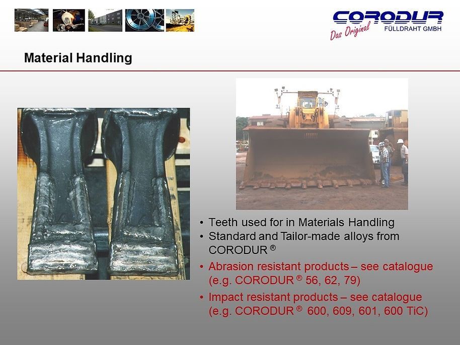
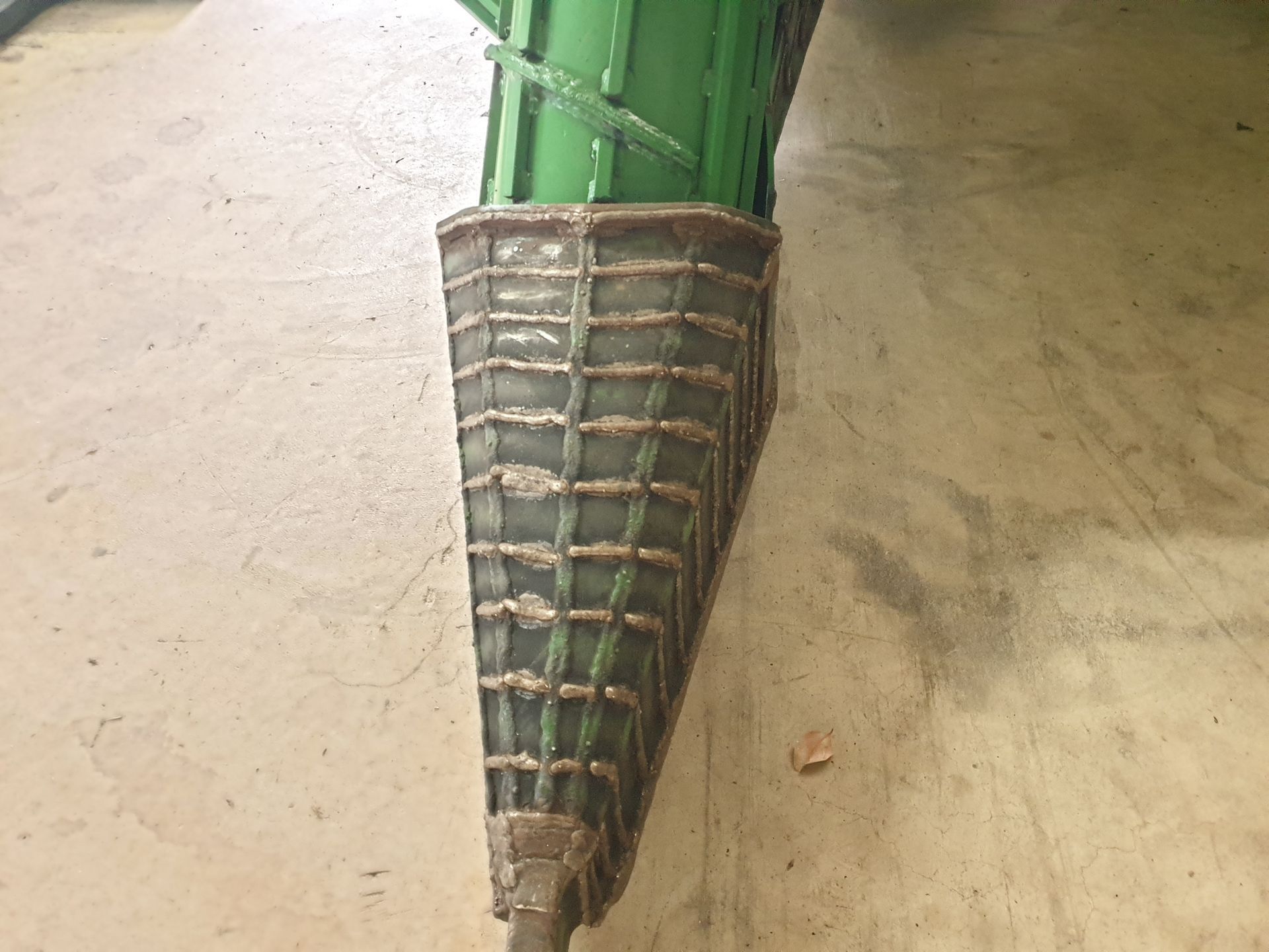
A Digger Bucket Tooth
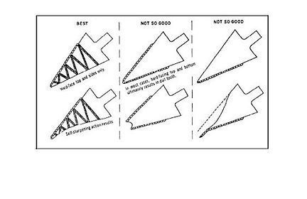
Consider hardfacing a digger tooth top, bottom and sides. Job done. All protected. Right?
Well TWO things will now surely happen:
1. With nowhere left to go, a proportion of the wear force will become directed head-on into the tooth tip. The rest of the abrasive force will head straight for the more expensive tooth-adapter!
2. After some time the wear forces will break through the tip of the tooth and reach the soft inner steel. This will wash out preferentially to its hardfaced sides and the tooth will end up blunted. The effort for the digger will be hugely increased as the tooth becomes a hindrance rather than a help to the digging process.
To counter these "next moves" by this dynamic wear force, we can take a further two measures in planning a hardfacing defence strategy:
* Only hardface the top and sides of the tooth, but not the bottom! This will direct the abrasive force underneath the tooth and the tooth will wear sharp. It will not blunt. So, the tooth retains a useful profile and remains in service longer and keeps the digger horsepower down.
* Hardface the tooth adaptor such that any remaining abrasive force is directed past this expensive item and on into the bucket where its energy dissipates.
What’s the best hardfacing pattern for my tooth?
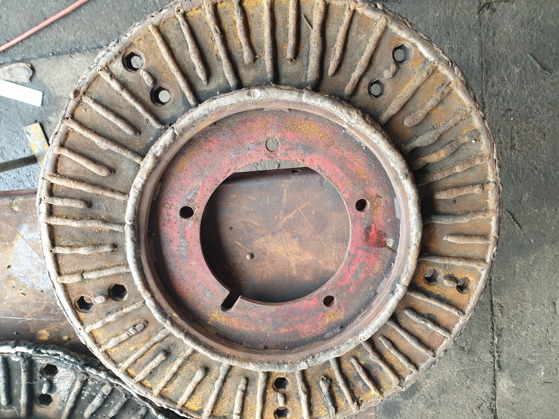
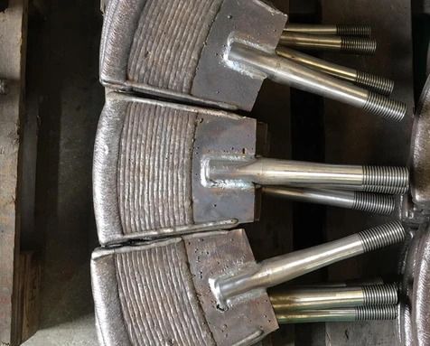
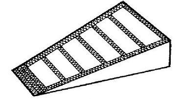
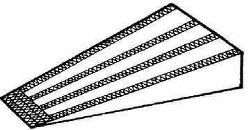
* If digging hard rock / aggregate, weld the hardfacing in Stringers and parallel with the direction of abrasive force. This will cause the hard quarry stone to ride over the tooth and into the bucket (use the same concept for the bucket lips and sides).
* If digging softer, finer material, weld the hardfacing at right angles to the direction of abrasion. This will trap the fines between the stringers and will cause build-up of material so that you are actually protecting against wear by using material against itself (use the same concept for the bucket lips and sides but in this case, you can also use cross-hatch and dot pattern, as long as it is able to trap the soil material).
Agricultural Points
The obvious strategy is to protect the front face of the point. A tungsten carbide tile is ideal if there are no impacts that might shatter it. However, this will cause the abrasive/erosive force to over the carbide tile face and "eddy" (circle) back in behind.
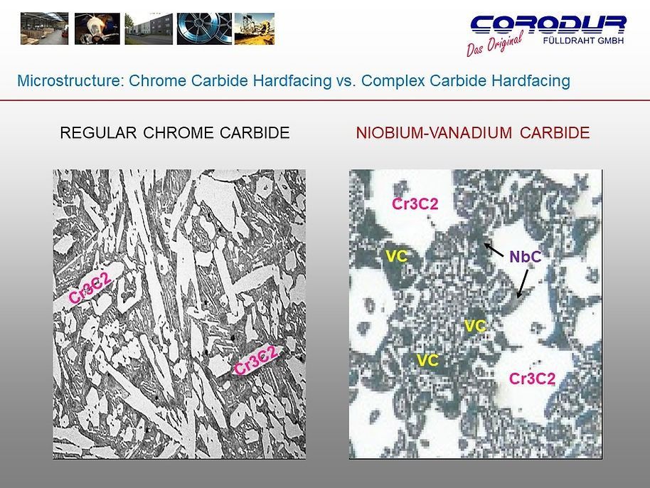
*The correct defensive strategy is therefore to weld a stringer or series of stringers of hardfacing at precisely the area where the deflected abrasive force comes back and hits the point (suggested hardfacing: COROCARB Ni60+ tungsten or CORODUR 79/81 composite).
Brick Mixer Paddle/Extruder Screw
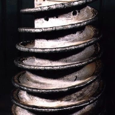
The critical area of the mixer paddle as well as the screw is the leading edge and approximately 30mm either side.
*Bringing the hardfacing a sufficient distance down the side of the paddle/screw edge will prevent undermining of the all important leading edges and so dissipate the wear energy at a low angle, out across the remaining flat area of the paddle/screw
Combination Strategies
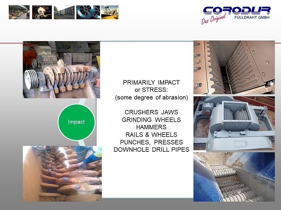
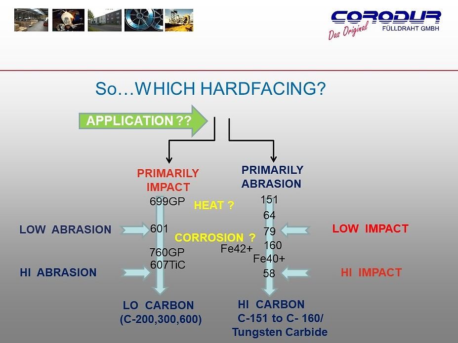
Some jobs call for combination strategies because wear forces are not always so simple. Quite often high abrasion can be accompanied by a degree of impact. Digger teeth may come under enormous grinding and impact pressure up against the face of the mine.
In this case consider applying a highly pressure-resistant hardfacing (CORODUR-58) at the point of the tooth and a highly abrasion-resistant hardfacing (CORODUR 79/81) in stringers away for the immediate impact area.
This strategy also works for GRIZZLY BARS where the "dump zone" is protected with a more impact resistant alloy.
Setting Wire Feed Tension
The Symptoms
The most common problem with mig welding is with the wire not feeding correctly. To keep things simple, lets ignore the feed rollers, wire type and polarity settings for the minute and focus on the actual arc of weld. The weld process itself is not that much different to the old “stick” welding that most are familiar with. In stick welding, the arc is ignited by coming close to the work to strike an arc and slowly feeding the electrode down into the weld as it is consumed. With MIG, the electrode is wire and instead of having to push it down into the weld, the feed motor pushes the wire out at the same rate as it is burned up.
As the weld is consuming the wire at a steady rate, any irregularity in the feeding of the wire can severely affect the arc. For instance, if the wire grabs for some reason and stops feeding for a split second, the arc will “climb” up the wire and burn it off at the contact tip. This is the most common complaint and usually the first step in where it all goes wrong for a lot of users. Usually, the first reaction is to increase wire tension a few turns to make sure that it doesn’t stick again, then try and continue welding. Increasing wire tension can actually give the same or worse results than not enough tension.
If we go back to basics, we have the issue of the wire burning onto the tip. Assuming that the wire speed adjustment is correct, this has most likely happened from the wire not feeding smoothly as discussed before. Before we do anything, we need to determine the reason for the wire slipping in the first place. Generally, the first item to look at would be if the drive roll is correct for the wire type and size. V-type rolls are for solid steel wire, U shape for aluminium and Knurled (serrated) for flux core and gasless wires. Next would be the liner inside the gun assembly and possibly the contact tip. The liner should be periodically cleaned and replaced. To clean the liner, remove the wire and blow compressed air in from the tip end back toward the welding machine. It is recommended to remove the gun assembly from the welder before this to prevent debris ending up inside wire feed unit. The liners can build up with dust/rust and other contaminants making it difficult for the wire to run smoothly. Liners are consumable items and do require replacing over time. Increasing wire tension will not correct this.
Tension Too High
The most common problem we see is the wire tension is far too high and “birds nest” of wire inside the feed motor assembly. This is from not correcting the feed issue as it occurs and just “cranking up” the tensioner thinking this is why it is not feeding. Having the tension too high deforms the cross-sectional shape of the wire as well as encouraging the wire to want to coil up. Trying to feed wire that wants to bend itself into a coil down a straight MIG gun is never going to end well, no matter how hard the machine tries.
Tension Too Low
It is rare to see a machine with too low of tension. The end result is that the wire slips and does not feed when pushed against the work. Tension should be increased in half turn increments until wire feeds correctly.
Setting Your Machine
Tension is not a one size fits all, nor is there any “charts” as every machine, wire and roller will be different. If you are running gasless wire for instance, you will have a knurled drive roll that has lots of grip on the wire. With this in mind you only need light wire tension where as a U roller for aluminium, you will need slightly more tension as it will tend to slip. This must be remembered when changing wire types in your machine. The best way to set wire tension is to cut the wire before it enters the wire feeder and pull out the remaining wire from the gun. Don’t pull wire back onto the spool as this wire may be deformed in shape having already been through the feed rollers. Remove the contact tip and wind wire tension off until it feels loose. Straighten the first 3 inches of wire out and feed through the rollers into the MIG gun. By straightening the wire, you are less likely to damage your liner.
REMOVE YOUR EARTH LEAD FROM THE MACHINE
This will prevent arcing in the next few steps. Pull the trigger or wire inch button to start feeding wire through the liner. If the rollers are slipping at this stage, increase tension ½ turns at a time until feed is resumed. Once wire is around 2” out of the gun end, replace contact tip and trim wire to about 1” from the contact tip. Firmly hold the end of the wire between the fingers WITH A GLOVED HAND and pull the trigger to feed wire. You should only just be able to make it slip. If it is slipping to easy, increase the wire tension in ½ turns as before. If you can’t make it slip, reduce tension by 1 turn and try again. Once you have found the correct tension, make a note of the setting for that type of roller/wire combination. If you have to increase this after a period of time you may need to look at cleaning or replacing the liner.
Remember, if it cant feed properly, it wont weld properly.
Locations We Service
Site Links
Specialised Industries
Welding Machines & Plasma Cutters
Locations
Trading Hours
- Monday
- -
- Tuesday
- -
- Wednesday
- -
- Thursday
- -
- Friday
- -
- Saturday
- Closed
- Sunday
- Closed
